Tip of the Day 32: The Sumitomo Oscillograph Interface
Even though not for everyone I include this tip because makes a good example of sequencing with a mixed bag of sequence and analog inputs signals. The original Sumitomo Oscillograph Interface’s days are numbered: Sumitomo is working on getting the eDART REDI kit up and running so as to have a standard interface with “hard” sequence signals. Nevertheless there are a number of them out there. So here’s the deal.
The original Oscillograph interface gives us a fixed set of outputs that hook to the eDART with the following names:
- Seq. Module Input / First Stage
- Plastic Pressure / Injection
- Stroke / Injection
- Velocity / Injection
- Revolution Rate / Screw Motor
Only the first one is an on / off signal that goes into the ID-7 sequence module. The others are all 0 – 10 V signals. The “sequencer function” takes care of turning this stew into Machine Sequence signals as follows.
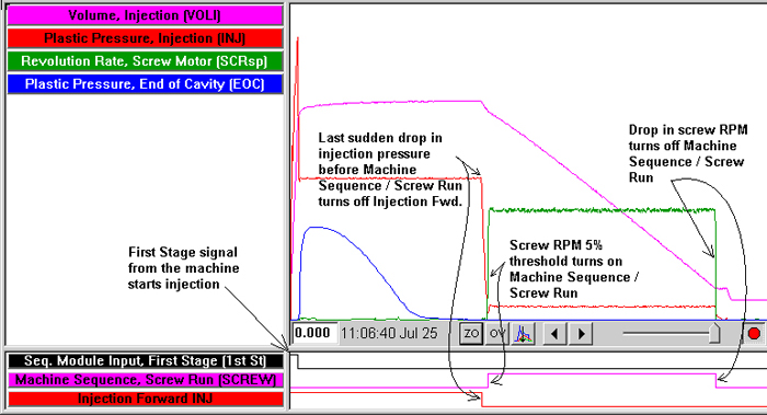
- Machine Sequence / Screw Run: Goes on when the Revolution Rate / Screw Motor is above 5% of full scale. Goes off when the screw speed falls below 1% of full scale.
- Machine Sequence / Injection Forward: On (cycle start) when Seq. Module Input / First Stage goes on; Off at last sudden drop in injection pressure before Machine Sequence / Screw Run comes on.
- Machine Sequence / Fill: On when Volume / Injection crosses zero (the position of the screw when the screw motor stopped). Off at Plastic Pressure / Injection Peak or a set fill volume, if set by the user.
Here is a graph to help illustrate this.