
3 Injection Molding Mechanics You Need to Know
There are many areas that require a deep understanding of mechanical in the industry. We will graze the surface of what you need to know about the machine, the intensification ratio, and the mold.
1. The Machine
Did you know that 80% of the energy required to melt the material comes from mechanical friction? The first step is understanding the Length to Diameter Ratio (L/D) (a comparison of its flighted length to diameter) in conjunction with the compression ratio (the reduction in depth of the space between the root diameter and outside diameter of the screw).
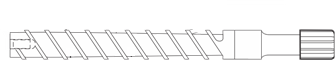
Figure 1 helps to understand if the design is efficient enough to melt the pellets before they are injected into the mold. Imagine rubbing your hands together on a cold day to generate heat. The faster your hands are rubbed together, the greater the heat. If they are pressed together firmly, the heat generated increases yet again. The reciprocating screw design works the same way. If a screw design is too aggressive, it can cause degradation. If it isn’t aggressive enough, it won’t work the way it needs to. So it’s vital to find the right balance.
2. The Intensification Ratio
The next type of mechanical advantage that must be understood on the molding machine is the intensification ratio. This ratio determines the amount of work, or power, the injection unit can deliver during the filling and packing phase.
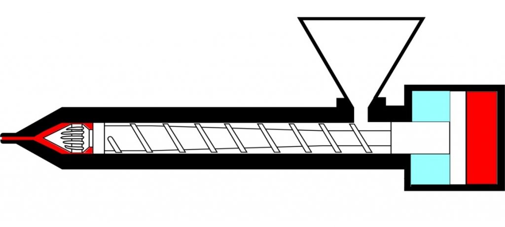
Hydraulic machines generally have large diameter cylinders in small diameter screws (shown in Figure 2). If we compare the area of the hydraulic cylinder to the area of the screw, the intensification ratio can be calculated. If this step is overlooked, the molded part may require more power than the machine can deliver, yielding an inconsistent process.
For example, if we apply 500 PSIh hydraulic pressure to a 10:1 ratio, the result is 5,000 PSIp. When the same pressure is applied to a machine with an intensification ratio of 15:1, the result becomes 7,500 PSIp. Think of it like a magnifying glass.
3. The Mold
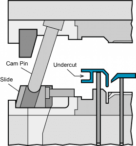
Now let’s center our attention on the mold and its mechanics. Many parts today are designed with undercut features that require movement of components, such as slides or lifters. It’s important to understand minimum and maximum angles for either to ensure the steel can be disengaged from the molded part. If the angle is too steep, there could be galling between the metal components. If it’s too shallow, the distance of travel required to release the part could negatively impact the mold size or place excessive stress on the lifter rod or cam pin (shown in Figure 3).
Conclusion
Mechanical is only one of six injection molding areas you need to master to become a plastics pro. Learn all of them in our latest white paper.