You just established a center process, now what? You probably record the machine setpoints on a setup sheet, right? You may even make the mistake of validating your process based off of these setpoints. But these don’t always directly correlate with the actual output.
Here’s an analogy for you: You have your cruise control set at 55 mph, but you are going down a steep slope and your speed goes up to 70 mph. A cop catches you and pulls you over—does he care that your cruise control was set to 55? Probably not. He only cares that you were going 70. In other words, the setpoint doesn’t matter, the output does.
Machinery Fades
The injection molding machine itself is a piece of machinery used to produce good quality plastic parts in tolerance and within the quoted cycle time. The key word there is machinery. What happens to any piece of machinery, whether it is mechanical, hydraulic, or servo driven electric? They are all prone to wear over time, and if you do not have a robust preventive maintenance plan in place, they will more than likely wear even faster than they are intended too. Once these machines start to wear, do you know if it is still hitting the setpoints you have entered into the controller?
Some machines have hundreds of setpoints, so let’s focus on a few that can have an impact on part quality.
Injection Speed Linearity Test
In our training courses, we teach about the Injection Speed Linearity test. This is one of the most important tests you can run on your molding machines to see how accurate the actual machine’s injection velocity is compared to the machine’s injection velocity setpoints. There are a few important factors that can have an influence on whether your machine can actually hit these setpoints.
One key factor is the actual shot size. If it is less than 20% of the machine’s maximum shot size, there is a good chance it is not hitting the injection velocity setpoint. Here’s another analogy: if you were offered any car of your choice for free but you had to hit 100 mph in 10 feet in order to receive it, would you be able to do it? Of course not. You wouldn’t have enough distance to obtain the necessary speed.
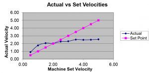
That same rule applies in injection molding machines. If you do not have enough shot stroke, the machine does not have a chance of hitting the actual injection speed you’re trying to achieve. Figure 1 shows an example of an injection speed linearity test using only 6% of the machine’s maximum shot stroke. The machine was set at 5 inches per second, but it was only able to achieve 2.5 inches per second. That’s not because it was a bad machine, but because it was running a mold that was below 20% of the maximum shot size we recommend.
Why Not to Use Hydraulic PSI
Surprisingly, we still find numerous molders that are recording injection psi and pack and hold psi in hydraulic psi. These pressure setpoints do not always produce the same part from machine to machine. That is mostly due to the difference in intensification ratios of the area of the injection cylinder to the area of the screw between the two machines. You also lose the ability to monitor viscosity shifts that you would see while monitoring the specific pressure during the filling phase of the process.
To help people understand this better, I like to use the analogy of playing darts. If you are standing back at the throw line, how hard is it to hit a bullseye on every throw? For most of us, it can be pretty difficult. This is like measuring the hydraulic pressure on the back of the injection unit. These setpoints don’t guarantee that the machine is producing the same part from shot to shot, day to day, or year to year. However, if we place cavity pressure sensors inside the mold and look at post gate pressure and end of fill pressure, that is like standing directly in front of the dart board.
Match Critical Cavity Pressure Data
As long as the sensors are placed in the proper location, we have data that can catch short shots, dimensional variation, pack rate, cooling rate, and gate seal (just to name a few). These are all considered outputs that can be monitored and can have alarm limits set around them to ensure you hit a bullseye every cycle.
This also makes it easier to match your process from one machine to another. Two machines may not perform exactly the same way, even if they are the same brand and the exact same specs. That means if you try to match a process based off of setpoints, you may end up with two completely different parts. However, if you were to match critical aspects of the data from cavity pressure sensors, you have a better shot of making the same part regardless of machine wear, viscosity shifts from the material supplier, or what machine it runs in.
Here’s another example: when you only look at the machine’s temperature setpoints, they are very rarely running exactly to the setpoint. Just to keep it simple, if you were to set all zones for the barrel temperatures at 460°F, how many of these zones would be exactly at 460° F? If you were to look at the controller at any given time, you may find one or two zones at this temperature but sooner or later, they are going to go higher or lower than the setpoint. How high or low depends on the machine’s temperature controller, PID loops, thermocouple placement, and the heaters themselves.
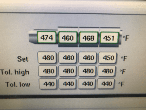
If you were to move this same mold and process to another machine, all of these variables may be different. Even if you use the same temperature set point of 460° F, you may see completely different temperature readings on the controller. If you figure in the different barrel sizes, residence time, and screw design between the two machines, you will find the actual melt temperature may be drastically different, even with the same process setpoints. Figure 2 shows the difference between barrel temperature setpoints and actual barrel temperatures of a machine controller.
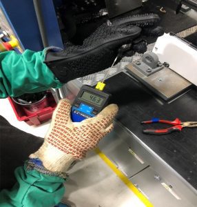
When we preformed a melt temperature test using a thin wire probe and a pyrometer, we found that the actual melt temperature was 463° F (as shown in Figure 3). Although in this case the melt temperature was very close to the machine setpoint, it is not always the case.
A great example of this was during a customer visit a couple of years ago. I was helping them investigate scrap issues between two different machines that were purchased at the same time from the same manufacturer and built to the same specs. They were running two identical molds with the same material and the same process set points. They couldn’t understand why one of the machines was running around 3% scrap but the other machine was running over 10% scrap. To their surprise, there was a 40° F difference in actual melt temperature between the two machines. Once they went away from matching the temperature setpoints and matched the actual melt temperature between the two machines, they were able to run similar scrap rates.
Machine Controllers Differ
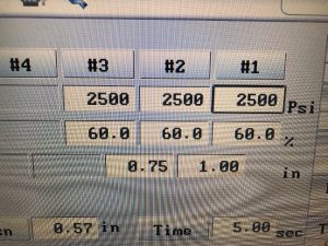
Some machine controllers will read different process setpoints in percentages. If you only record the percentage setpoint, it can get you in trouble in the future if you do not record the actual as well. There is nothing wrong with a machine that reads in percentages, however while running these machines there are two important variables that must be considered: the maximum for this setpoint and the actual output.
In Figure 4, it shows a machine controller that reads the injection flow rate in percentage. If you don’t know what the machine’s maximum injection flow rate is, then how will you ever know what 60% is? If you have one machine that is capable of 10 inches per second and another that is only capable of 8 inches per second, this 50% can be a huge difference in injection flow rate. It doesn’t mean that either machine is not capable of producing good parts, it just means that 50% is not the same setpoint between both machines. In a case like this, it would be important to record the volume of material you are injecting and the actual fill time of the process. If you inject the same volume of material in the same amount of time, then you are matching the volumetric flow rate for this process, which makes it much easier to replicate the validated process every time it runs.
Molders often need to revalidate processes because the setpoints they have validated no longer produce the same quality part. In today’s market, molders have to be as cost effective as possible to be competitive, and if you are continuously revalidating your process it eats away at your profits. At the end of the day, you are going to be more successful if you monitor and record process outputs instead of the machine setpoints. This gives you the ability to match the validated process regardless of any machine wear, viscosity shifts, or machine changes.