
TZERO®: What We Do and How We Do It
A journey through the creation of the Design Pod
By Jeremy Williams, Consultant/Trainer
RJG is known industry-wide for its Master Molder™ class and eDART® System, but do you know about our TZERO® program? Often the name can throw people for a loop, so let me start by explaining its origins.
For those of you who are familiar with mold building, T0 is the first time a mold sees plastic after it is designed and manufactured. In our industry, rarely does the mold or part meet all of its requirements at T0. On a regular basis, gates must be enlarged, vents added, or steel groomed. Unfortunately, this leads to T1, or the second trial for the mold. Often times there are days or weeks between T0 and T1 depending on the complexity and quantity of changes needed. We have seen molds reach T10 or higher before they get through the validation protocol (PPAP or IQ/OQ/PQ).
In order to better explain what TZERO does, I will walk you through the process we went through in order to create the Design POD. The Design POD is a tool used to show the effects of both good and poor design practices, which can yield typical molding non-conformities. Here are the typical 7 steps TZERO walks through before the steel is even cut to ensure good parts are made from the very first shot.
1. Part Design
Early on in the project, it’s important to think about how the raw material will be converted into its final form. If this is not considered, then there can be costly delays in the program reaching launch.
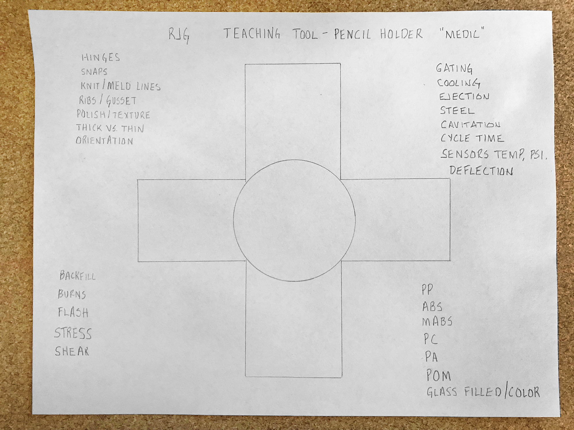
One purpose of the Design POD is to create a training aid for the Part Design and Mold Design course that would promote good manufacturing processes (GMP), while showing common mistakes. Below in Image 1 is the first sketch of what that product might look like. Let’s just say the napkin sketch needed a “few minor modifications” before moving forward.
2. Print
The next step is to ensure that the needs are met by providing a print or drawing that communicates the requirements to the mold builder and the molder.
This is often overlooked and can be detrimental if not properly evaluated for GMP drawing practices, datums, tolerances, accuracy, color, etc. shown above in Image 2.
When all of the details are not called out properly, it can lead to confusion of what the designer needs and how the mold maker or molder interprets the drawing. This doesn’t mean that it must be a critical dimension, but it must be identified so that it can be measured to ensure that it meets specification limits.
Our advice is to not leave it to chance—if it’s important to the product, clearly identify the requirement. Otherwise, there could be a costly and time-consuming engineering change to follow.
3. Material Selection
“Just select a plastic, it will be fine.” We hear this a lot from designers, but it’s not their fault in many circumstances. They don’t understand that just because we can find a plastic that will meet the flexural, load, or temperature requirements doesn’t mean that we can use it. Not all materials are suited for injection molding, so a careful evaluation of the material properties might reveal that it’s meant for an extrusion or blow molding application, which will create major difficulties with injection molding.
In this application, there were several areas that needed to be considered. First, the living hinge design would dictate that we need a high MFI (Melt Flow Index) polypropylene (PP) to ensure proper hinge function.
Next on the list was working with the marketing department, which is always a “favorite” of engineers. The Design POD required a very specific brand color that needed to blend with the Pinnacle PP 1335 Z with an MFI of 35 g/10min that was being sourced through Ashley Resins. After a couple of trials for color matching, marketing selected UN66083 Fresh Green from Clariant.
4. Simulation
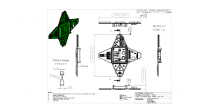
Simulation is a powerful tool to help us understand and predict what will occur during the molding process. It can give an insight into some potential assembly or secondary operations that could be negatively impacted based on the molded product. It’s important to use simulation as a predictive tool so that the part design, material, or mold can be modified before the first shots occur. There are many areas that simulation can be used to look at pressures, temperatures, warp, and a host of other areas. For this part, the thin living hinge section (0.406 mm or 0.016 in.) and transition from thick (3.00 mm or 0.118 in.) to thin (0.75 mm or 0.0296 in.) were areas of the highest concern. We needed to understand where the end of fill would occur so a sensor could be properly placed to detect short shots during molding. We understood all limitations and made design changes accordingly. Below in Image 3, we can see the simulation model with the part, full hot runner system, and water.
Simulation can also predict the cavity pressure where the sensors can be placed, thus allowing a template to be transferred between the simulation package(s) and the eDART®.
5. Mold Design
Selecting the right mold designer and builder is another critical step in the process. Each has a niche market in which they excel. For this project, we had small details, moderately tight tolerances, complex mold requirements in a tight space, and (as always) a tight deadline. We chose to partner with Ameritech Die and Mold in North Carolina because of their high-quality molds and proximity to RJG’s Hangar facility in the region, where the mold would live out its days.
With the preliminary work done with simulations, we were able to provide Ameritech with hot runner sizes, water line designs, and sensor locations to help reduce design iterations on their end.
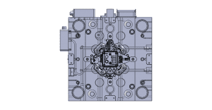
Above in Image 4, we can see the final mold design after a single design review meeting. The mold contains five cavity pressure sensors, two Thermocouples, and one Mold Deflection sensor. This design will be utilized for R&D purposes over the coming years at RJG.
Due to the living hinges, we had to ensure the polymer chain orientation during fill was perpendicular to the living hinge, otherwise we would likely yield a single use hinge (which was not design intent).
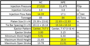
6. Molding Machine
It would be ideal if our single cavity, single gated part only had to ever run in one machine, wouldn’t it? However, we live in reality and this is rarely the case in molding. The scheduler needs the flexibility to run a mold in at least two machines, if not more.
Knowing this information at the onset of a project helps to provide a more accurate representation of what is needed for the long haul. Without it, production could be backed into a corner with only a single machine to run production in. This could cause missed shipments for a multitude of reason. Given the JIT (Just in Time) environment that molders are forced into on a regular occasion, this is not the ideal situation.
In this circumstance, we have to design for the least capable machine. Regularly, we have a new electric machine and a vintage hydraulic. We cannot take these at face value and presume the electric always has the highest capability.
There are many other areas that must be considered, but these are starting points:
- Injection Pressure
- Injection Volume
- Injection Flow Rate
- Tonnage
A line-by-line comparison of each machine is the best method to match the correct mold and machine. Otherwise, Murphy or Karma are likely to rear their unwelcome faces. Image 5 shows the two machines side by side. We can see that the highlighted fields create a virtual machine that has the lowest possible capabilities.
7. Processing
Given the material, challenging thin wall geometry, and machine capability, we simulated both Decoupled II and III processes to determine which would be the best for all of these factors. Simulation will not allow us to transfer from the fill phase to pack via cavity pressure, but it does allow us to transfer when the cavity is 100% full by volume and, in turn, closely replicate a Decoupled III process.
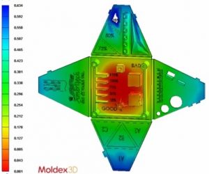
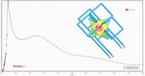
Above in Image 6 is an example of running a Decoupled II process with a fill time of 0.63 seconds and fill only transferring when the cavity is 92% full by volume.
With a slow flow rate, varying wall thickness, and multiple changes in geometry, the process yielded high injection pressure, elevated tonnage, and a short shot that could not be influenced during the pack phase.
Through multiple iterations, we determined there was a process window to produce parts within all the constraints, but that the window was narrow at best.
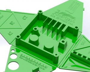
The objective was to demonstrate the effects of poor design on manufacturing. In this case, we hit the nail on the head with nearly every molding defect represented in a 48-second cycle.
Conclusion
We can see through these seven stages that TZERO collaborated with designers, marketing, material suppliers, machine manufactures, mold makers, and more to create a viable product that met everyone’s needs. The final product does not look a lot like the initial napkin sketch, but through a rigorous evaluation, we were able to create the final product seen in Image 7.
The focus of TZERO is to be a single source solutions provider for plastic injection molded parts by evaluating all aspects from the plastic’s point of view. Our goal is to minimize mold trials, reducing the amount of time and money required to reach validation.
We get involved as early as the napkin sketch stage but can step in at any point from design through manufacturing to help push the product over the finish line.