Tip of the Day 146: Late Pressure Rise in Post Gate
We have been asked several times of late to explain why the post gate pressure should rise toward the end but during hold. This is a phenomenon seen most commonly in thick, low pressure loss parts made in semi-crystalline materials and with hot runners.
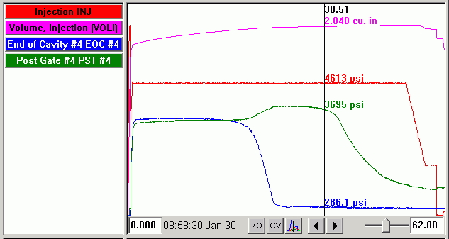
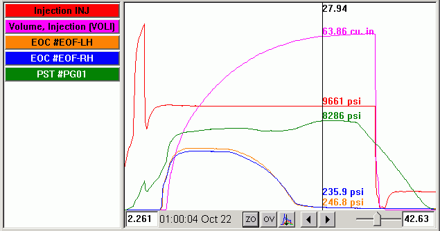
We see this easily in our lab on our Husky research mold when it is configured with the hot runner manifold. This part is 4 mm thick. Here is an example of a D2 process with late post gate rise running polypro.
What is happening?
The first reaction is to say that there is mold deflection. While it is conceivable, this shot has 3300 psi in the two cavities. The force on the clamp is only about 16 tons† (~10 in2 total). The clamp is 55 tons and the curves do not change when clamp pressure is adjusted. So let’s think of the physics of what is going on.
The part fills and packs very early in the cycle. But during hold more material continues to flow because of the shrinkage due to crystallization. You can see this by scaling the volume curve so the bottom is about the value when the cavity is first “packed” and the top is near the peak.
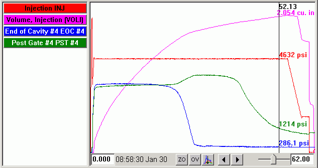
You can see that the flow (depicted by the volume curve) is significant during hold and has a discontinuity or roll-off when the end of cavity crystallizes and shrinks away from the sensor. It is probable that there is some check-ring leakage because the forward screw motion does not quite stop even when the post gate area is frozen. Nevertheless, there is flow during hold. About 13% of the total part weight flows in during hold. This we tested by closing the gate early and comparing the less-than-finished part with one made with full hold time.
Now, the nozzle, runner and gates behave like an orifice. Flow through an orifice results in a proportional pressure drop. Here the pressure drop is from hold to the sensor. As the end of cavity area crystallizes the flow begins to drop off. Less flow, same orifice results in a lower pressure drop. So the rise in gate pressure is due to the drop from hold decreasing with decreasing flow. The runners and gates stay open (hot runners) and the gate area takes longer to freeze (hot area around the gate).
This explanation is backed up further by having run a simulation of this mold. We did not have the exact material data. But using a generic polypropylene produced similar curves in the simulation.
Conclusion:
Decreasing flow at the end of shrinkage time decreases pressure drop and so increases post gate pressure.
I have included some more examples below in case you have time to read further.
†If that triggers a memory, we know how old you are.
Another Explanation Suggested in Discussion with our Consultant(s):
We are familiar with the idea that when a cavity pressure goes up there is a driving force pushing more material in. In these cases what is happening is that, during shrinkage flow, the driving force is lost: ΔP across the runner system reduces the driving pressure supplied by hold pressure. When flow dies off the ΔP lowers and more of the driving force (hold pressure) appears at the sensor. Whether it puts much material in is doubtful. This could be tested.
Equation available here.
Extra Examples
Here is an example from simulation.
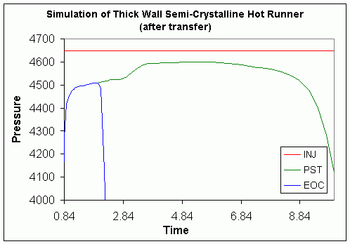
This is not strictly an accurate representation of our Husky mold. It is something like a quarter of a cavity. But you can see the similar pressure rise in the post gate sensor as the end of cavity freezes and flow decreases.
In these next graphs has the volume curve is again scaled up to see better how the screw moves.
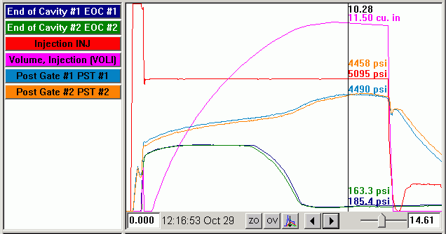
In the mold above the flow rate is steadily declining, probably due to wall thickening. This part is only about 2 mm thick. So the post gate pressure rises in a slope as the flow decreases and the pressure drop from hold to PST decreases. The small drop after the end of hold is a slight discharge of material as hold pressure drops before the valve gate pin can physically move to closed.
The mold above is an example of a mold with a cold sub-gate runner fed by a hot runner. In this case the sub-gates try to freeze at or near the same time the rest of the part is finishing flow. You can still see the post gate rise as flow declines.
The shot-to-shot variation in the post gate pressure quite large. We think this is because the flow and gate freeze point (or at least choke-off point) are tightly connected. A very tiny change in flow can cause an early or late gate freeze. I am not sure if the discontinuity at the end of the post gate curve (where it starts its cooling slope) is due to a gate closure or sub-gate freeze.