
Part Design Considerations for Manufacturability Optimization
Part concept and design are vital elements to the molding process. Because of this, it is highly encouraged to spend some additional time analyzing your design before creating the mold. Significant opportunities to decrease waste and time-to-market can be achieved with some up-front work.
Factors that should be well-thought-out for part design are:
-
Part functionality
-
Molding machine and performance
-
Plastic material selection
-
Universal process
-
The impact that these choices have on mold complexity
-
Possible gate locations
For the purpose of this article, we will focus on part design itself, specifically wall thickness.
The Most Vital Rule
If there was only one rule for the injection molding part design, it would have to be to maintain uniform wall thickness.
Prior to part ejection, injection molded parts must be cooled down from processing temperatures to a point where they are able to maintain their shape and withstand the forces of removal. Once the plastic makes contact with mold steel, it immediately begins to cool. During this period, wall thickness alone is the driving factor in overall part quality (dimensions), solidification time, stress, and overall cycle time (time to part ejection).
That said, determining the correct wall thickness for your application can have drastic effects on the cost and production speed of manufacturing. Wall thickness has no set restrictions and will typically be driven by the size and structural requirements of your plastic part along with the resin type and flow length needed. Choosing a thinner wall can yield overall cycle time reductions at the penalty of some physical characteristics (strength, chemical resistance, flame retardant properties, etc.). Inversely, thicker walls can help with these characteristics while increasing cycle time and manufacturing costs.
Cooling Time
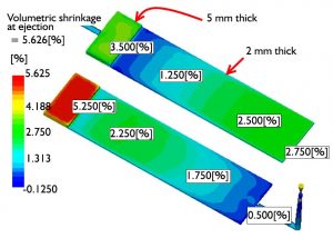
In regards to the effect on cooling time, a general guideline is that your cooling time will increase with thickness^2. Why thickness^2? To help explain this, we will use a 2 mm wall and 4 mm wall (shown below).
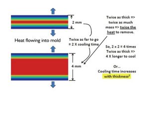
When you look at a cross section of the 4 mm wall, you can see that all the heat has twice as far to travel before it can exit the part. The other factor is that you now have twice as much material that’s trying to be an insulator. Thus, you could take whatever cooling time you had with the 2 mm section and multiply it by a factor of 4 to come up with your new plastic cooling time.
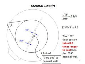
Alternatives
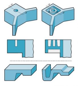
If your part is so complex that you need variations on your wall thickness, consider alternatives, such as coring or using ribs in areas of concern.
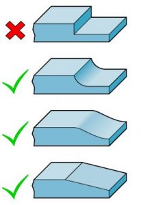
Also, remember that sharp corners cause stress concentrations in molded parts. If you must make transitions in wall thickness, gradual transitions can help reduce pressure losses through the part, giving better overall dimensional control.
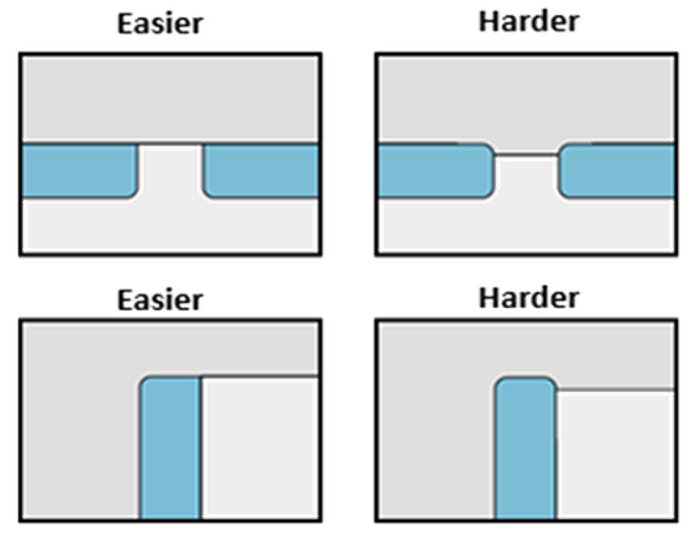
Part Design Affecting Mold Design
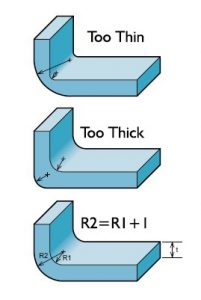
The overall design of the part impacts the mold design. If a part requires a radius for cosmetic reasons, reducing concentrated stress areas, or part functionality, it is important to keep in mind how this decision affects the mold design. The graphic below shows radii relating to mold parting line location.
The ease of part ejection from the mold is the responsibility of the part designer. A plastic part should always be designed with draft to reduce friction to prevent the part from sticking. Draft is essential if the molded part has surface texture. The deeper the texture the more draft that is required.
Think of part design and mold design as the two sides of a seesaw. As the part complexity increases, the mold loses simplicity. When part complexity decreases, the mold becomes more simplistic.
Possible Gate Locations
Gate location plays a significant role in the overall part quality in areas such as: flow length and pattern (ie aspect ratio & area of influence), shrinkage uniformity, cosmetic issues, and part performance to name a few. An optimized gate location reduces the pressure gradient across the molded part, thus allowing dimensional stability.
Conclusion
There are many creative ways to deal with the trickiest design requirements. The challenge that we have to deal with the most is convincing the OEM that the part design needs to be altered to provide a better processing window. The issues that have been discussed thus far simply cannot be “processed out” and can be a burden on the molder for the life cycle of the tool. Getting the molder, tool shop, and OEM involved and communicating early on in the process is key to the overall success of any complex project. If you’d like assistance in getting the mold right the first time, RJG’s TZERO® program is an engineering/consulting service that helps molders with the mold design and concept process.