
Cavity Pressure Selection Options and Solutions
Whether you are a first time user or a seasoned veteran, cavity pressure selection and placement can at times be a confusing decision. That’s why we have more options than ever to fit your application to make you successful.
When I worked in our customer support department, we started with a simple question: What problem are you trying to solve? Is it short shots? Flash? Dimensions? You want to put a transducer where the problem is, plain and simple. For most of you that is going to be the last place to fill or what we commonly refer to as the end of cavity. The majority of quality defects can be correlated to the pressure at this location. Too much pressure and the parts get bigger, not enough pressure and the parts get smaller. All in all, a pretty straight forward correlation.
When determining the end of cavity, we typically just ask customers to produce a short shot and place a sensor closest to that location. If the tool hasn’t been built yet, a flow simulation study can help determine that last place to fill. Short of that, experience and gate location is also an option for determining the end of cavity location.
“But wait, Mr. RJG guy, I have a multi-cavity mold, how do I put transducers in those tools?”
In this case, we start with whether it’s a cold runner or hot runner tool. If it’s a cold runner mold, the flow pattern will be consistent. Typically, we can reduce the number of transducers necessary by putting a sensor at the end of cavity in the cavity that fills last. This strategy works pretty well up to about eight cavities. As cavitation increases beyond that, so will the number of transducers. So what about hot runner tools? In this case, the previous strategy starts to get challenged and the reason for that is the thermal cycling that occurs in hot runner manifolds and tips. The flow pattern has a tendency to change over time, so the number of transducers will need to go up to be able to catch quality defects.
What about flush mount or ejector pin style sensors? This is simply determined by availability and real estate. Do you have an ejector pin in the location of the last place to fill? If yes, then that is the route that we will typically take. If the answer to that question is no, then a flush mount sensor may need to be used.
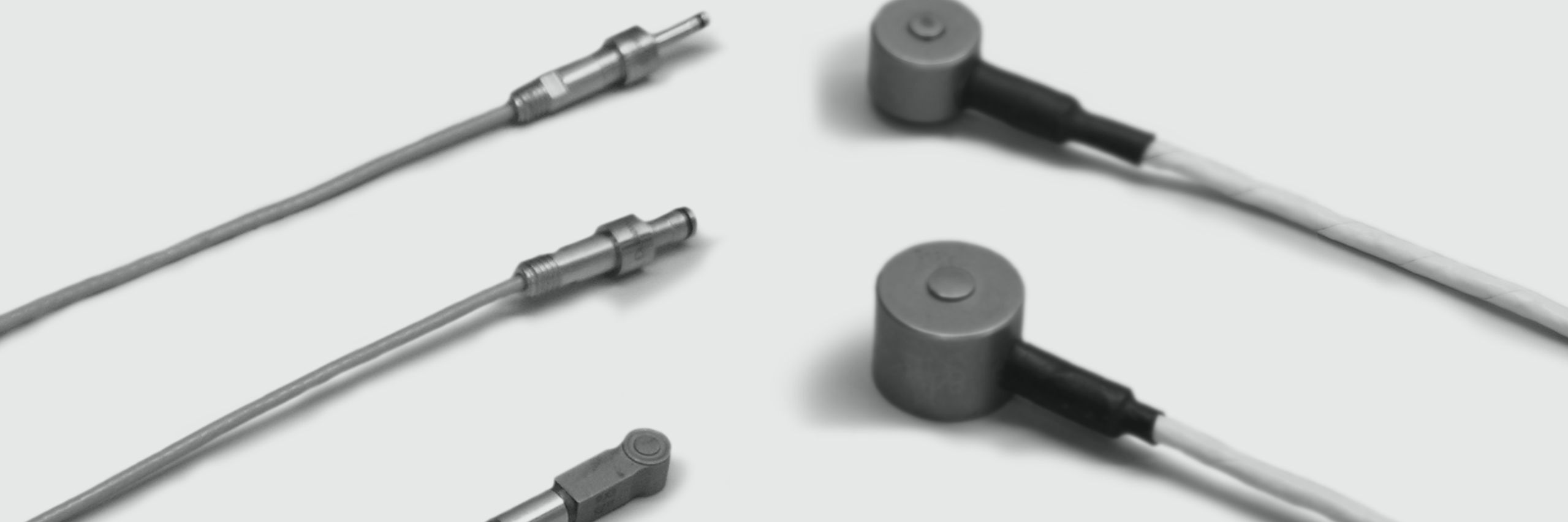
How do you know if you want to use piezoelectric or strain gauge technology? First, all flush mount sensors are piezoelectric, but ejector pin transducers come in both technologies. Strain gauge is the cheaper of the two, and until now, piezoelectric came in smaller sizes that we can better utilize in small parts. Our new 6 mm strain gage sensor matches the performance and size of the smallest piezoelectric sensor head at a more cost effective price. In the end, sensor selection comes down to what technology best fits your application.
Another option that we have started offering recently is a multi-channel setup. For customers who had high cavitation molds, the number of connectors and wires became an issue. To alleviate this problem, we developed a multi-channel solution for both piezoelectric and strain gauge sensors. This drastically reduced the number of connectors and wires and therefore reduced breakage to these components.
As you can see, there are several choices to be made and solutions to be discovered. If there are ever any questions about how to instrument your tools, contact your friendly customer support representative so they can help you provide absolute quality parts to your customers.