Tip of the Day 185: Sensor Placement: “Put the Bandage where it Hurts” †
When I was working with a customer on a part similar to that in tip #183 we were planning sensor locations. Of course we jumped first on the idea of last place to fill.

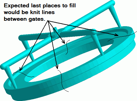
As would seem logical we thought, “To find a short shot, put the sensor where the flow fronts join together furthest from the gates.” Of course there are four possible spots and we might need to pick only one. But it seemed like a good idea at the time.
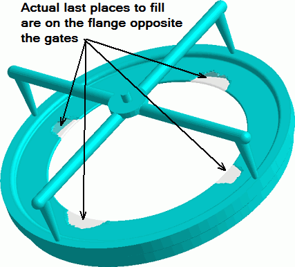
As you recall from #183 it turns out, becasue of freezing, that the thin flange makes the part fill last on the flange opposite the gate like this…

Shot – no goal.
So let’s put an ejector pin on the flange near the gate.
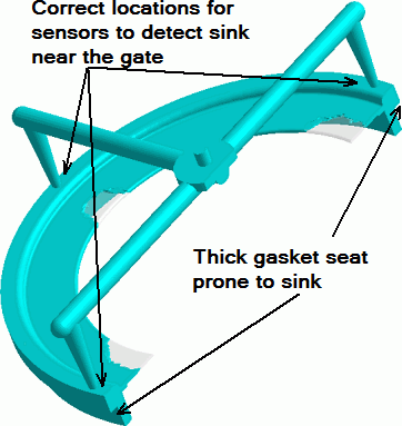
But then we found out that short shots are NOT the problem. In fact, the problem is under-packing near the gate. This causes a sink in the thick section and a bad seal with a rubber gasket. Another shot – no goal.
If we had located a sensor at the edge of the flange (as above) it would be frozen too early to “see” the under-pack condition in the thick section. Instead we selected a position near the first gate to freeze as the monitoring sensor location.

What do we learn from this? Here are some general principles for locating the “bandage” (an in-cavity sensor) to score a goal; i.e. to get the most value for effort.
-
- First, ask “What hurts?” That is, define the problem you are trying to solve.‡
-
- Place the appropriate sensor near the location where the problem is so that it can “see” the changes that cause the defect.
-
- Sensors can be used for V->P transfer control (switchover) to improve consistency. They should be in the “area of influence”: A place that the machine can still drive plastic at the time the switchover is to take place.
Control sensors do not guarantee quality everywhere in the cavity. More to come on control sensors later.
† The title for this one comes from Denis Fecci, charter employee of RJG France.
‡ Some quality problems and the data we need to see them:
-
- Pressure Related (cavity pressure sensors):Sink, short, flash, void, dimensions, weight, chemical resistance, warp or in-molded stress (pressure difference across the cavity)
-
- Flow Rate Related (timing between cavity temperature or pressure sensors):Paint or chrome adhesion, blush etc.
-
- Temperature Related (cavity temperature sensors or back-slope on pressure):Cooling circuit variation, imbalance or blockage => warp due to semi-crystalline shrinkage behavior, improper melt temperatures.