Make Your Molds Machine and Location Independent by Utilizing In-Cavity Pressure Data
Proving process capability to the customer is very time consuming and costly, and if that isn’t bad enough, customers require molders to re-prove capability each time their mold is moved to a different machine. Molders need a way to prove to customers that they can mold the same quality parts in different machines and be able to provide solid data to prove it. In-cavity sensors can help provide this data, allowing molders to save time and reduce costs.
Traditional Methods and Where They Fall Short
Traditional methods of proving capability to customers rely heavily on process and part documentation. The process documentation often includes machine set-points for temperatures, speeds, times and machine pressures. The part documentation includes extensive part measurement data from controlled production run-offs. Other information may be included, such as plans to ensure continued quality in the future, but the primary information is related to the process and the part.
The problem with this method arises when the molder needs to move the mold to an alternate machine. In today’s world of just-in-time delivery, the molder competes by shuffling jobs to alternatively capable machines as they become available. Moving molds to different machines is inevitable. If the process documentation is based on machine settings, it is logical that customers would want process capability re-verified whenever their mold is moved to a new machine.
So what’s a molder do? Take the time and expense to re-prove the capability on new machines when circumstances dictate moving the mold – or take a new approach and avoid this increased cost of quality all together?
An Effective Alternative – Use Cavity Pressure Data to Prove Capability
True process capability relies on consistent delivery of four key plastic variables inside the mold cavity: Plastic Temperature, Flow-Rate, Pressure Gradient, and Cooling Rate & Time. When these four plastics variables are matched, the same part will be created, regardless of which machine the mold is run in.
Plastic melt temperature:
The melt temperature is the temperature of the plastic as it is delivered into the mold. Barrel temperatures (whether actual measured values or set points) should never be assumed to represent the actual melt temperature. Often, the actual melt temperature can vary from the barrel temperature settings by up to 200 C. The melt temperature can also be affected by screw RPM, screw geometry, and back pressure. While in-mold temperature measurements are difficult to obtain, the effect of melt temperature can often be seen in the cavity pressure curves — hotter material takes longer to cool and depressurize inside the cavity.
Plastic flow rate:
This is the flow rate of the plastic inside the mold, not the screw speed profile itself. The actual flow rate depends on the diameter of the screw, the injection speed used, the consistency of check ring seating, and even on the size of the cushion. Flow rate can be measured directly using cavity pressure sensors. These sensors can detect the time at which melt arrived at the sensor, which is directly related to in-mold flow rate.

Plastic pressure gradient:
The pressure of the plastic inside the mold is one of the most important factors impacting part quality. Too much pressure and the part flashes – too little and the part is short or has sinks. Dimensions, texture, and part strength are also related to in-mold pressure. Unfortunately, it is difficult to determine the in-cavity pressures using only machine data. Cavity pressure data is a precise measure of the pressure inside the mold, independent of machine or location.
Plastic cooling rate / time:
The plastic cooling rate is the difference between the melt temperature and the temperature of the mold cavity steel. Like melt temperature, it is difficult to measure this directly. In-mold thermocouples can give a good indication of steel temperature inside the cavity. Cavity pressure sensors can also provide an indirect measure of cooling by monitoring the rate of depressurization in the mold.
A “template”, or in-mold snapshot of the ideal process, can be created and saved electronically capturing all of these plastic conditions at any given moment in time. A template gives the molder data-based targets, independent of machine or location, to help replicate the same plastic conditions in future molding cycles. These powerful templates are obtained through the use of in-mold cavity pressure sensors in combination with a process monitoring and control system.
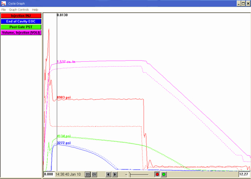
The following graphical process data illustrates how far off machine set points can be from true in-cavity conditions. Figure 1 shows a process template that has been “matched” by adjusting the machine set points as needed to create the same plastic pressure inside the mold cavity. The template was created using an electric molding machine with a toggle clamp unit. The matching process was later developed in a hydraulic molding machine of equivalent tonnage with a similar shot capacity.
Notice how much different the machine pressure and volume curves are in this captured cycle in order to duplicate the same pressures inside of the mold cavity. Imagine the difficulty in trying to make the same part without using in-cavity data. All four plastic variables would have to be matched largely by trial and error. Using in-cavity data allows the four plastic variables to be matched quickly and precisely with real data instead.
Of course the customer still requires evidence that the “matched process” has actually molded product that meets their specifications. This involves simply measuring a number of parts molded at the accepted process conditions and proving with measurement data that they consistently meet the specifications.
Using the cavity pressure templates as machine independent verification that the process conditions are met, in combination with part measurement data that proves the customer specifications are met statistically, is the ultimate means of proving capability.
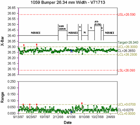
Let’s look at an actual example of dimensional data from a production process. The data shown below was taken from a mold run on three machines where the in-cavity template was matched at each setup. This particular job was run, monitored, and controlled over a two-year period. Figure 2 shows the dimensional data taken from SPC checks throughout the run. Both the X-Bar (average measurement) and Range (process variation) remain identical, regardless of machine.
In summary, the use of in-cavity data allows identical parts to be molded on a wide variety of machines, reducing or eliminating the costs of re-qualifying the process each time the mold is moved. The use of process templates will significantly reduce the time it takes to set-up a job in an alternate machine, providing a cost saving to the molder. This technology is not new – it has been used successfully in production environments for over 20 years. This approach can provide a critical advantage to molders looking to reduce costs and improve quality.
