In today’s global economy absolute quality to the customer is the world standard for any successful molder. While all molders talk about world class Lean Manufacturing and total quality, the fact is that most are still attempting to “sample and sort” their way to total quality with little success.
Is there available technology to allow totally automated quality for injection molded parts?
In this article we will describe the relationship between common reject types and how the use of cavity pressure sensors can be used to detect and contain these abnormal events.
Ask any group of molders whether or not they have sent their customers any bad parts in the past year and the reply is fairly predictable: nervous laughter and an “of course”. When we ask for a list of the most probable causes, the list always looks like this:
- Short Shots
- Flash
- Sinks and Voids
- Dimensional Problems
- Warp
- Gloss Gradient
- Splay
- Specks or other Contaminants
- Off Color
This list would be the same anywhere in the world, usually in the same order of frequency.
In order to gain the ability to detect and contain abnormal parts using cavity pressure technology, we must first have an understanding of each molding defect.
Short Shots:
Most understand what a short shot is but when asked to put a numerical value on it, molders and customers alike have a hard time defining it. When it is defined as 0 or Zero they seem even more confused. We have to go on to explain that the absence of plastic in the part also means that no pressure was developed in the unfilled section of the cavity. Typically a minimum cavity pressure of 3000 PSI or 200MPA is required for properly packed parts. When a short shot is viewed from this perspective, we simply have to detect a 200 MPA change in cavity pressure and sort out the parts to totally eliminate short shots from getting to the customer.

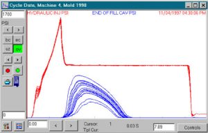
Figure 1 shows machine Hydraulic Pressure and End of Cavity Pressure overlaid over several shots showing variation, resulting in short shots.
Flash:
With short shots defined numerically it is easier to define a flashed part made in a properly clamped, undamaged mold. It is an excess of plastic pressure, which deflects the mold open enough to allow the plastic to flash over the cavity parting line. Flash and excess packing often results in parts sticking in the mold with resultant mold damage. If a mold is never allowed to flash or parts to stick due to over packing, flash will be eliminated. Setting upper cavity pressure alarms and sorting parts will eliminate flashed parts from getting into the Good Part box.
Sinks and Voids:
Sinks and voids are both a result of localized under-packing of the cavity and/or a lack of gate seal. All of this shows up as a change in the cavity pressure in the area of the problem. A cavity pressure sensor strategically placed will exhibit the problem.
Dimensional Variations:
As plastic is packed into the cavity after the mold is full it is compressed between 3/4 and 1% per 100 MPA. If the effective cavity pressure across a critical dimensional area of a part changes 100 MPA, the dimensional area will vary around 1%. Crystalline materials may vary even more, especially if cooling varies. If cooling does vary, the shape of the curve will vary during cooling, which can be detected by software. This allows parts to be contained. Dimensional variations in parts can be detected by monitoring the cavity pressure curve shapes and gradients from the gate end of the parts to the end of the cavities. If this pressure gradient is maintained over time part dimensions will be maintained.
Warp:
Warp is non-uniform part distortion as opposed to shrinkage variation overall. Changes in warp are caused by changes in packing, cooling rate and cooling time. All of these show up in the cavity pressure waveform. Cooling can also be monitored by monitoring coolant temperatures and pressure drop across mold manifolds in order to detect plugged water lines, changes in water flow and incorrect temperature settings.
Gloss gradient:
Many times on cosmetic parts, a variation in gloss is evident. This often occurs from the gate area toward the end of the cavity. Gloss gradients often relate to the rate and amount that the part is packed. Controlling the rate of packing and thus the shape of the cavity pressure curve allows gloss gradients to be eliminated or made consistent.
The remaining defects on the list: Splay, Specks/Contamination, and Off Color issues may not be detectable by cavity pressure data. A small black spec, for example, or a slight color difference typically will not affect the in-cavity conditions. These problems can be very difficult to detect and are usually tied directly to the material itself or other pre-process issues.
Containment:
Armed with the knowledge above it is simple to devise a strategy for abnormal part containment. With real time data from inside the mold cavity for pressures, times, time to pack, integral values, etc, alarm limits can be set to detect most all part defects.

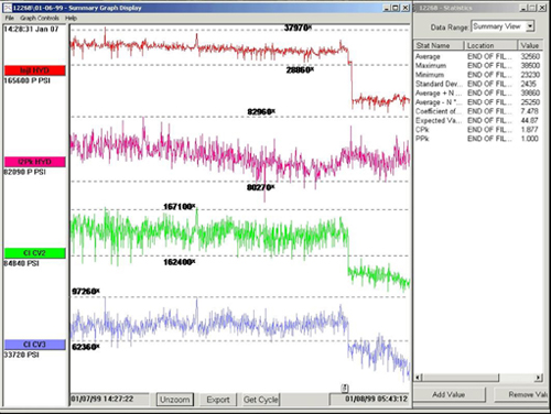
Figure 2 shows summary data values with alarms set for detection and containment.
If an alarm condition is detected, a signal is sent from the eDART System™ to some means of automatically containing the abnormal parts. Robots, reversing conveyors, and flipper chutes are commonly used, but any device that can accept an input signal and divert the parts to a “suspect” location may be utilized. This strategy of using cavity pressure sensors to contain abnormal parts opens the door for molding companies to provide total quality to the customer and eliminates the winless battle of trying to sort to today’s expected quality levels.
